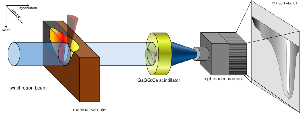
The following schematic diagram describes the phase contrast videography procedure using the example of a laser welding process on copper. During the laser process, the sample is irradiated from left to right by the synchrotron radiation.

Due to a difference in density in the process phases (solid, liquid, gaseous), the sample is penetrated to different degrees by the X-ray beam. If the transmitted radiation is projected onto a suitable scintillator material, a luminous phenomenon is formed on the scintillator depending on the phase contrast. This image is then recorded by a high-speed camera, allowing the process in the material to be visualized. The temporal and spatial resolution of the images depends on a number of factors. These include the flux density and area of the X-ray beam, the material and geometric properties of the material to be x-rayed, the type and geometry of the scintillator and the high-speed camera available.
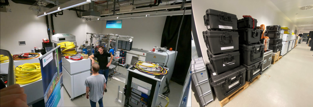
A modular and flexible setup is required to carry out the tests in order to meet the requirements of the processes. This includes control elements, robot technology, sensors and a variety of laser beam sources and optical systems. The following picture shows the equipment that was transported to DESY in Hamburg during the past measurement campaigns.

A large number of different laser beam sources can be used, which operate continuously, pulsed or ultra-short pulsed, and emit from the visible to the near-infrared wavelength range.
Do you have any further questions? Please feel free to contact us! We look forward to answering all your open questions.
